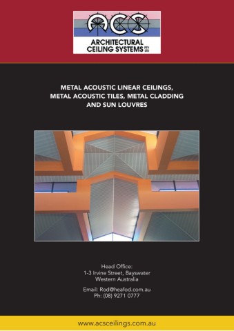
METAL ACOUSTIC LINEAR CEILINGS, METAL ACOUSTIC TILES, METAL CLADDING AND SUN LOUVRES Head Office: 1-3 Irvine Street, Bayswater Western Australia Email: [email protected] Ph: (08) 9271 0777 www.acsceilings.com.au
INDEX INTRODUCTION Linear Acoustic Ceilings Architectural Ceiling Systems (ACS) has been a part of Ministrip Broadline 3.................................................................................... the Australian building industry since 1965. Now part Alumacoust Mk l and Mk ll 4................................................................ of the Heafod group of companies, ACS started as an Linear 5 and Forms 5................................................................................... acoustic ceilings contracting business which quickly Spac Deckform 6............................................................................................. gained a reputation for the ability to carry out large and Coruline 7-9.......................................................................................................... complicated installations. Profiles and Integrated Systems 10............................................... Harmoni 11-13................................................................................................... Development of our own range of specialised metal acoustic Wall & Soffit Cladding tiles and ceiling systems along with the addition of a factory Deckform Cladding 14............................................................................... and machinery complex to manufacture new ACS products set Profile 230 15....................................................................................................... the foundation for the company’s growth. Acoustic Modular Metal Acoustic Ceiling Tiles I.C.E - Setback 16............................................................................................ Successful expansion into national and international I.C.E - Levelo 17................................................................................................ markets set ACS as a leader in the design, manufacture I.C.E. - Coffer 18............................................................................................... and distribution of metal ceilings and wall systems. Plafond - Divisions within the Heafod group work together to Variable Module Metal Ceiling Tiles 19.................................... provide design, manufacture and distribution solutions Audibar - Sound Barrier Ceiling System...........................20 to architects, contractors and developers. This vertical Sun Louvr Systems integration of our production provides our customers with Skoolouvr - Robust 21................................................................................. time proven and quality controlled products that deliver Alumashade - Aluminium 22................................................................ the best outcomes possible. As a result ACS is the market Nodril - Partition Head Fixing System................................23 leading producer for metal ceiling and wall systems in Agents and Distributors....................................................................24 Australia. ACS provide innovative and highly effective systems suitable for use in the following segments: *Office *Retail *Institutional *Public Space *Industrial *Healthcare *Education *Hospitality *Residential *Transport *Sporting *Communications *Performing Arts *Correctional. DESIGN With a concept in mind, ACS explores the various options and develops a design, utilising its diverse resources of skills and technology. In many instances this leads to registered designs and patent registrations. ENGINEERING Colrol, Australia’s leader in Cold Roll Forming machine line manufacturing, provides the Group an engineering element, vital to the development of its new and increasing product range. SALES & MARKETING From the original design stage through to project hand over ACS offers the services of its Technical Sales Team to Architects, Designers and Consultants alike. CEILINGS & LINING PRODUCTS That will last for the life of the building.
THE ECONOMICAL ACOUSTIC CEILING SOLUTION MINISTRIP BROADLINE Ministrip has proven to be the most successful linear ceiling system in the Australian market today. This is achieved through providing an economical system with features such as Acoustic and Thermal control, pre- finished strips, a pleasing aesthetic, strength, durability, quick installation and no wet trades required. The Ministrip system is a low profile, open style with a 75mm module available in a selection of finishes; Colorbond, Powder Coated, Clear Laquuer over Zincalume Steel base metal. Ministrip offers a high degree of impact resistance and is suitable in a wide range of applications. The face panel is available in non-perforated or a variety of perforation options. For over 40 years, a large percentage of West Australian Educational buildings continue to have Ministrip installed. 44.5mm ALPHA 1.0 0.9 7mm Gap 0.8 ACS Universal Linear Carrier Rail ACS Universal Linear Carrier RaAilCASCUS nUinvieversrsaall LLiinneeaarrCCaarrrierireRraRil ail 0.7 0.6 0.5 0.4 0.3 0.2 0.1 125 250 500 1 K 2K 4K FREQUENCY 1 NRC = 0.60 PERFORATED + 25MM BTF 2 NRC = 0.80 PERFORATED + 50MM BTF Prod7u5cmt Pmrofile Produ7c5t mPromfile PPrroodduucctt PPrroofifliele 3 NRC = 0.45 NON-PERFORATED + 25MM BTF 4 NRC = 0.65 NON-PERFORATED + 50MM BTF Products of Unequalled Popularity 3
THE MOST ADVANCED LINEAR CEILING SYSTEM THE MOST ADVANCED THE MOST ADVANCED LINEAR APAleurmLfoaUrcaotuMesdtAMoAKLrT1PUChHlaa-MsiOPnEbeerAefMUConrCadSEteOesOdcITrLiLobSIUrLeMINTPdNISlaNbGiAyTnKEaE-rAMDclAShitRYVKeRcStAlsTanNEdMCED CEILING SYSTEMdesAiglunmeras casouthset M‘pKre1shtigaes’blieneanrdceislcinrgibseydstbemy .architects CEILING SYSTEM Maanunfdacdtuerseigdnfreorms aasluthmein‘ipumresittigheas’ alinbeoaldr cceoinlivnegxsfyascteempa.nel THE MOST ADVANCED AlumLIaNcEouAstRMK1 ALUMACOUST MKlthaMt maankuefsaactsutyrelisdhfsrotamteamluenmtininiuamn oitpheanssatylbeo1ld00cmomnvmexodule. 1.0 CEILING SYSTEM 0.9 Thefascysetepmancaenl tahlsaot mincaokrepsoaratsetyalischlosstaurteempaennetl iinnfaillnand is 0.8 avaoilapbelne isntyplela1in00omr-pmPeermfrofoorardateuAtdeledlp.uaTohmnreePlassla.yicsnteo-mucsatnMalsKo1 0.7 iAnlcuomrpaocroautest aMcK1lohsuarsebpeaennedl iensficll raibneddisbayvaariclahbitlecints 0.6 Alumacoust MK1palnadindoerspigenreforsraatsetd10h..09 epa‘pnreelst.ige’ linear ceiling system. ALPHA 0.5 0.4 Manufactured fro0m.8 aluminium it has a bold convex 0.3 Alumacoust MK1 depth face panel that1.0m00..a67 kes a stylish statement in an 0.2 27mm 0.1 depth 1.0125 250 500 1 K 2 K 4K oinpceonrpsot1yr0al0emtem10a0mc000l...o879ms000...u345mreo10dp0muamlnee. lTihnefillsyasntedmisALPHAcan alsPoroduct Profile 27mm available in 0.9 FREQUENCY depth 15mm 0.8 NRC = 0.60 PERFORATED + 25MM BTF 4 1 0.7 ALPHA100mm 100mm02.6 NRC = 0.80 PERFORATED + 50MM BTF Produpct lParoifnileor perfora0t.e6 d0.2 panels. 03.5 NRC = 0.40 NON-PERFORATED + 25MM BTF ALPHA 0.4 NRC = 0.50 NON-PERFORATED + 50MM BTF 0.5 0.1 4 0.3 0.2 depth 0.4 27mm 125 250 500 1 K 2 K 4 K 0.1 0.3 FREQUENCY 125 250 500 1 K 2 K 4K FREQUENCY 0.2 100mm 1 NRC = 0.60 PERFORATED + 25MM4B4T.F5mm 0.1 1 NR1C00m=m0.60 PERFORATED + 25MM BTF Product Profile 2 NRC = 0.80 PERFORATED + 50MM BTF 2 NRC = 0.80 PERFORATED + 50MM BTF 4K 3 NRC = 0.40 NON-PERFORATED + 25MM BTF 125 250 500 1 K 2 K 4 NRCA=C0AS.C5U0SnUNinvOievNers-rPsaaEllRLLFiinOneeRaaArrTCECaDarrr+ierir5eR0raMRilMailBTF 3 NRC = 0.40 NON-PFERREQFUOENRCAYTED + 25MM BTF 1 N4RCNR=C0=.600.5P0ENRFOONR-PAETREFDO+RA2T5EMDM+ 5B0TMF M BTF 2 NRC = 0.80 PERFORATED + 50MM BTF Product Profile 3 NRC = 0.40 NON-PERFORATED + 25MM BTF 44.5mm 4 NRC = 0.50 NON-PERFORATED + 50MM BTF Product Profile 44.5mm Alumacoust MK11ACASCUSnUinvieversrsaall LLiinneeaarrCCaarrrierireRraRil ail ALUMAALUCMOAUCSOTUMSTKMllKll- Perforated or Plain - 1.0 PerAflourmaatecdouosrt MPlKa2inprovidACeASsCUaSnUicnvievoernsrsaatlel LLmiinneepaarorCrCaaarrrrie4ryire4Rar.a5Rnilmadiml 0.9 Aloloumkmioandcoeourunr srltaoMnogkKe2inopofrouorvpirdaeennsgsaetyoclefoconepteielimnngpstopyralaenrcyeelasi,lninsdtgillmoondaern 0.8 Product Profile 0.7 ALUMACOUST MKll1Zi0n0caapmaalupmlnumeemrimlnfsoe,ioursaamdtitnluleodolderni.nCpAaaop-v1nlPaoa0eeiril0bnalr.mfoboAonmClrreaASdaCtimUneSZpnidUonaienvdclioervuauferromsPrllsPPeaurraroialol.nlmaddLLtAiuiuiiuenennccvemedttaa-aaPPrrirprnolCooafCdaiafrleibarlnCreriilenreeiorelRpi.rlnoalRailrabiniloonrd ALPHA 0.6 Product Profile 0.5 0.4 0.3 Alumacoust MK11 0.2 0.1 1.0125 250 500 1 K 2 K 4K Alumacoust MK2 provides a contemporary and 0.9 FREQUENCY 4K 0.8 100mmProduct Profile 0I.7 NRC = 0.50 PERFORATED + 25MM BTF 02.6 NRC = 0.70 PERFORATED + 50MM BTF ALPHA 03.5 NRC = 0.40 NON-PERFORATED + 25MM BTF modern look in our rangAeluofmoPrpoadeuncctsoPtryoufleilescteMilingK11 0.4 NRC = 0.50 NON-PERFORATED + 50MM BTF panels, still on a 100mm module. Available in 04.3 0.2 0.1 aluminium or Colo1r.0bond ZincParoludumcteParonfidle in plain or 125 250 500 1 K 2K a perforated pane00..89l. FREQUENCY I NRC = 0.50 PERFORATED + 25MM4B4T.F5mm PrPordoduucctt PProrfoilefile 0.7 Alumacoust MK11 0.6 2 NRC = 0.70 PERFORATED + 50MM BTF ALPHA 0.5 100mm 100mmProduct Pro3fileNRC = 0.40 NON-PPrEoRduFcOt RPAroTfEileD + 25MM BTF 4 NRC = 0.50 NON-PERFORATED + 50MM BTF 1.0 0.4 ACASCUS nUniviveerrssaall LLinineeaar rCCararirerrieRraiRl ail 0.9 0.3 PPrroodduucctt PProrofifleile 44.5mm 0.8 0.2 0.7 0.1 The Classical Styled Linear SystemACASCUS nUniviveerrssaall LLinineeaar rCCararirerrieRraiRl ail 0.6 125 250 500 1 K 2 K 4 K 4 0.5 FREQUENCY ALPHA PPrroodduucctt PProrofifleile depth ACS Universal Linear Carrier Rail ACS Universal Linear Carrier Rail ACS Universal Linear Carrier Rail ACS Universal Linear Carrier Rail 15mm 0.4 I NRC = 0.50 PERFORATED + 25MM BTF 100mmProduct Profile 0.3 2 NRC = 0.70 PERFORATED + 50MM BTF 0.2 0.1 3 NPRrod1Cu0c0t=Pmrom0file.40 NON-PEPRroFdOu1c0tRP0rAomfilTme ED + 25MMPrPordoBduTuccFtt PProrfoilefile 4 NRC = 0.50 NON-PERFORATED + 50MM BTF 4K 125 250 500 1 K 2 K FREQUENCY TheLiCnelaaTsrshiSceyasltCeStmlyalesdsical Styled Linear Systemdepth 15mm I NRC = 0.50 PERFORATED + 25MM BTFACS Universal Linear Carrier Rail ACS Universal Linear Carrier Rail ACS Universal Linear Carrier Rail ACS Universal Linear Carrier Rail 2 NRC = 0.70 PERFORATED + 50MM BTF
CEILINGS FOR THE DISCERNING DESIGNER LINEAR 5 100mm Module Linear 5 is a most popular style in our open linear range. Linear 5 combines clean sharp lines within a classical, balanced visual. Available in aluminium or Colorbond Zincalume in plain or three perforation options, band, fully perforated or bridge. Ideal for use in education, institutional and public buildings it has the aesethics and acoustic performance to enhance these environments. Linear 5 is a low profile open style product in a 100mm module. A large percentage of schools in Western Australia have had Linear 5 installed over the past 35 years as testament to its classic style. ALPHA 1.0 0.9 80mm 0.8 0.7 Product Profile 0.6 0.5 0.4 0.3 0.2 0.1 FREQUENCY 1 NRC = 0.65 BAND PERFORATED - 25MM BTF 2 NRC = 0.75 BAND PERFORATED - 50MM BTF 3 NRC = 0.55 UNPERFORATED - 25MM BTF 4 NRC = 0.65 UNPERFORATED - 50MM BTF 5 NRC = 0.70 BRIDGE PERFORATED - 25MM BTF 6 NRC = 0.85 BRIDGE PERFORATED - 50MM BTF 7 NRC = 0.65 FULL PERFORATION - 25MM BTF 8 NRC = 0.80 FULL PERFORATION - 50MM BTF 100 125 160 200 250 315 400 500 630 800 1K 1.25 K 1.6 K 2K 2.5 K 3.15 K 4K 5K Depth ACS Universal Linear Carrier Rail 13mm FORMS Round Hole Perforated or Plain Forms offers an added dimension in depth through a 22mm deep face panel within a 75mm open style module that delivers excellent acoustic outcomes. Forms provides a bold distinctive profiled face panel that is available in plain and two perforation types. ALPHA 1.0 0.9 44.5mm 0.8 0.7 0.6 0.5 0.4 0.3 0.2 0.1 FREQUENCY 1 NRC = 0.70 BAND PERFORATED - 25MM BTF 2 NRC = 0.75 BAND PERFORATED - 50MM BTF 3 NRC = 0.75 FULL PERFORATION - 25MM BTF 4 NRC = 0.85 FULL PERFORATION - 50MM BTF 5 NRC = 0.45 UNPERFORATED - 25MM BTF 6 NRC = 0.60 UNPERFORATED - 50MM BTF ACASCUSniUvenrivsaelrLsianleaLrinCeaarrr iCerarRraiiel r Rail 100 125 160 200 250 315 400 500 630 800 1K 1.25 K 1.6 K 2K 2.5 K 3.15 K 4K 5K depth 23mm 75mm 75mm Product Prof ile ProPdroudcutcPt roPfriolefile Appealing Asset Protection 5
THE MOST ADVANCED LINEAR CEILING SPAC DECKFORM Special Acoustic Ceiling Deckform The SPAC Deckform system was developed to cater for the needs of Architects and Designers desiring an inaccessible system with the optimum of resistance to vandalism or abuse. Manufactured from 0.75mm Zincalume steel in a 150mm wide module closed style system. For those applications not demanding high security requirements, SPAC Deckform system can be produced in a 0.55mm BMT, providing a more economical option. Each face panel interlocks one to another and is supported by a concealed carrier system providing an attractive monolithic appearance. The system has been used in Prisons, Correctional facilities, Public Changerooms, Sports Stadiums, Bus and Rail Stations providing a high degree of security and protection of assets and services. SPAC Deckform is available in perforated forms and various finishes such as Colorbond, Baked Enamel, Powder Coat or Clear Lacquer over Zincalume. 15 5015 1550 15 SECURITY DFIEXCIKNFGO:RHMDEECACLVKAFYDODDRIMNUGTCYLACDADCRAINRGIREIERRCRAARILRIER RAIL 44.5 40 150 40 150 44.5H4E0AVY DUTY CARRIER 40HEAVY DUTY CARRIER SPAC DECKFORM STANDARD CARRIER RAIL SPAC DECKFORM STANDARD CARRIER RAIL 20 20 36 PERFORATED PANELS 150 36 CARRIER RAIL PERFORATED PANELS 150 CARRIER RAIL ALPHA 1.0 0.9 0.8 0.7 0.6 0.5 0.4 0.3 0.2 0.1 100 125 160 200 250 315 400 500 630 800 1K 1.25 K 1.6 K 2K 2.5 K 3.15 K 4K 5K FREQUENCY 1 NRC = 0.65 PERFORATED + 25MM BTF 2 NRC = 0.75 PERFORATED + 50MM BTF 6 Appealing Asset Protection
CORULINE CORULINE 7 Flexibility and Strength in Design
A RETURN TO A PAST CONCEPT USING MODERN SYSTEMISED TECHNOLOGY CORULINE SPECIFICATION Coruline panels shall be installed strictly in accordance with the manufacturers recommendations and the installer shall be responsible for the neatness and strength of the overall installation. Generally, provide ACS P/No. 4 black faced universal carrier rails spaced 1200mm* apart and spanning not more than1800mm* between hangers. Hangers shall be 25x25 angle compression hangers as supplied by the manufacturer and shall be Tek screwed to purlins and ACS P/No. 4 carriers. Fix Coruline face panels (perforated or unperforated) 160mm wide** by means of screws or rivets as recommended by the manufacturer through the fixing flange on one side of face panel. Continue to install face panels applying edge pressure on each panel appropriate to acieve a firm fixing. Face panels shall be standard ‘Colorbond’*** and shall be corrugated to provide 6 ribs per panel. All fixings and raw metal edges shall be concealed. Coruline face panels shall be perforated with 3mm diam. holes at 7mm crs. in a diagonal pattern. Perforations shall cover a width of 120mm of each face panel leaving 40mm unperforated at the side junction of each of the panels. Acoustic and thermal insulation, to a thickness of (25, 50 or 75mm) shall be black faced with non woven scrim or black polyester of an appropriate density and finish, which is to be laid over ceiling panels between the up-stand legs of the carrier rails. Wall trims to be ACS P/No. 21 Aluminium Wall angle in baked enamel finish matching colour, securely fastened to walls at 600mm centres alternatively use removeable wall finishing system. NOTES: * Security ceiling applications may require carrier rails to be installed at 600mm centres and spans reduced considerably. ** The 160mm module width of face panels may vary slightly, say 0.5 to 1mm depending upon metal type and installer practice. *** Standard Coruline face panels are as follows:- Standard white Colorbond over Zincalume steel of 0.40mm thickness (BMT). Other metal (such as Aluminium), metal thickness and colours may be requested from the manufacturer by the specifier. For the installation of Coruline in recreation centres of all types the added advantage of neat face “stitching” at strategic points should be discussed with the manufacturer. NOTE If a desired use is for a indoor recreation, please ask for our special recommendations in instalation. DEPTH: 7.5MM NOM. 160 Cover ACS UNIVERSAL DEPTH: 7.5MM NOM. TAEECSCAURNRIVIEERRSPAT.L4 TEE CARRIER PT.4 PRODUCT PROFILE PRODUCT PROFILE 8 Flexibility and Strength in Design
REVOLUTIONISING TIMELESS APPEAL WITH MODERN INNOVATION ORIGIN OF CORULINE CorulineTM is an innovative adaptation of a timeless cladding profile that maintains great appeal to the specifier and client for even the most modern of building applications. The inherent strength and character developed by such a profile provides many potential uses not previously realised. Coruline’s strength and flexibility in a great variety of aesthetic and practical ways leads us all to appreciate the ingenuity of its profile even further. Its appearance is accentuated by utilising our proprietary rolling methods that creates panels of long lengths. The aesthetic appeal of concealed fixings and other benefits of the Coruline System enable it to be used in applications for ceilings, walls, eaves and soffits.When installed in accordance with the manufacturer’s recommendations, CorulineTM can be used in areas requiring additional resistance to high wear and tear and climatic conditions whilst still providing an appealing and desirable finish. The Coruline range of Perforated and Unperforated Ceilings, Eave and Wall Linings turns the appeal and strength of miniature corrugated metal into a sophisticated and innovative system. Options • Colourbond Zincalume • Clear Lacquered Zincalume provides “Authentic look’ finishes. • Stoved Enamel (non-standard colours) • Aluminum Anodised or Painted. Features • Concealed Fixing • Perforated and Unperforated • Minimal end joins • Low traditional profile • Purpose rolled lengths • Acoustic or non-acoustic • Strong Machine Curve Rolled Carriers Applications • Curved, Flat and Raking Ceiling and Walls • Suspended or direct fixed • Decorative Finishes ZINCALUME ALPHA 1.0 Colorbond • Clear Lacquer 0.9 ANODIZED PERFORATED Powder Coat 0.8 OVER ALUMINIUM ALUMINIUM 0.7 ALUMINIUM 0.6 COLORBOND CLEAR LACQUER Powder Coat 0.5 OVER ZINCALUME OVER ZINCALUME 0.4 ACOUSTIC ASSESSMENT 0.3 Acoustic Performance - 0.2 Laboratory Tests Available 0.1 Open Area ≈ 15% FREQUENCY SIMPLE CONCEALED FIXING 1 NRC = 0.70 PERFORATED + 25MM BTF 2 NRC = 0.85 PERFORATED + 50MM BTF 3 NRC = 0.90 PERFORATED + 75MM BTF 100 125 160 200 250 315 400 500 630 800 1K 1.25 K 1.6 K 2K 2.5 K 3.15 K 4K 5K Premium Acoustic & Thermal Properties 9
ACS PRODUCT PROFILES MINISTRIP BROADLINE baked enamelled, to a colour to be selected from the ACS Colour Range. The panels shall have a substantially flat face Provide ACS4A Carrier Rails, spaced at 915mm apart, purpose Rolled profile appearance, spaced from each other suspended below upper supports and spanning not more leaving a 7.5mm gap. Acoustic and Thermal Insulation to the than 1800mm between gangers. The Carrier Rails shall provide thickness (25, 50, 75mm) shall be black faced with a non-woven machine spaced and shaped clips to accept Ministrip Ceiling Scrim and shall be laid over the Ceiling panels and between panels at exactly 75mm centres. The clipping face of the Carrier the upstand legs of the Carrier Rails. Rail shall be Matt Black painted. Ministrip Ceiling panels (non- perforated or perforated) shall be Cold Roll formed strip and ALUMACOUST MK1 selected from the ACS Colour Range. The panels shall have a bold convex face profile of 28.5mm depth, spaced from each Install ACS4C Carrier Rails spaced at 1200mm apart, other leaving a 12.7mm gap. Acoustic and Thermal Insulation suspended below upper supports and spanning not more in a thickness of (25, 50 or 75mm) shall be black faced with a than 1800mm between hangers. The Carrier Rails shall provide non-woven scrim, and shall be laid over the Ceiling panels and machine spaced and shaped clips, to accept Alumacoust MK between the upstand legs of the Carrier Rails. Closure strips (if 1 Ceiling panels at exactly 101.6mm centres. The clipping face required, plain or slotted for ventilation) shall be fitted as the of the Carrier Rail shall be Matt Black painted. Alumacoust installation of the face panels progresses. MK1 Ceiling panels (non-perforated or perforated) shall be Cold Roll formed strip and baked enamelled to a colour to be ALUMACOUST MK11 strip and baked enamelled, to a colour to be selected from the ACS Colour Range. The panels shall have a purpose Rolled Provide ACS4D-A or 4D-S Carrier Rails, spaced at 1200mm shape profile 1.5mm concaved face appearance with splayed apart, suspended below upper supports and spanning not edges 82mm x 15mm deep, and will be spaced from each more than 1800mm between hangers. The Carrier Rails other leaving a 18mm gap. Acoustic and Thermal Insulation shall provide machine spaced and shaped clips, to accept to the thickness (25, 50, 75mm) shall be black faced with a Alumacoust MK 11 Ceiling panels at exactly 100mm centres. non-woven Scrim and shall be laid over the Ceiling panels and The clipping face of the Carrier Rail shall be Matt Black between the upstand legs of the Carrier Rails. painted. Alumacoust MK 11 Ceiling panels (non-perforated or perforated) shall be Cold Roll formed (Steel or Aluminium) BAFFLIGHT - LOUVRES PRE-CURVED CARRIER RAIL The unique ACS Roll Formed `T’ profile carrier rail which is the universal carrier for all of the ACS Linear Strip range can now be purpose curved to a specified radius. Please consult with our Technical Sales Team regarding limitations. Pre-curved carrier rails from ACS now ensure easy and accurate curved sections for those special vaulted ceiling applications. LINEAR 5 colour to be selected from the ACS Colour Range. The panels shall have a purpose Rolled profile flat faced square cornered Provide ACS4E Carrier Rails, spaced at 1200mm apart. appearance 81mm x 12mm spaced from each other leaving a Suspended below upper supports and spanning not more 19mm gap. Acoustic and Thermal Insulation to the thickness than 1800mm between Hangers. The Carrier Rails shall (25, 50, 75mm) shall be black faced with a non-woven Scrim provide machine spaced and shaped clips to accept Linear 5 and shall be laid over the Ceiling panels and between the Ceiling panels at exactly 100mm centres. The clipping face of upstand legs of the Carrier Rails. the Carrier Rail shall be Matt Black painted. Linear 5 Ceiling panels (non-perforated or perforated) shall be Cold Roll formed (Steel or Aluminium) strip and baked enamelled, to a FORMS selected from the ACS Colour Range. The panels shall have a purpose Rolled profile flat face with 7mm radius lower Provide ACS4A Carrier Rails, spaced at 915mm apart. corners 67mm x 22mm deep and will be spaced from each Suspended below upper supports and spanning not other leaving a 7.5mm gap. Acoustic and Thermal Insulation more than 1800mm between hangers. The Carrier Rails to the thickness (25, 50, 75mm) shall be black faced with a shall provide machine spaced and shaped clips to accept non-woven Scrim and shall be laid over the Ceiling panels Forms Ceiling panels at exactly 75mm centres. The clipping and between the upstand legs of the Carrier Rails. face of the Carrier Rail shall be Matt Black painted. Forms Ceiling panels (non-perforated or perforated) shall be Cold Roll formed strip and baked enamelled, to a colour to be SPAC DECKFORM colour to be selected from the ACS Colour Range. The panels shall have a purpose Rolled flat closed profile with central Provide ACS4F Carrier Rails, spaced at 1200mm apart. rib 11.0 x 0.50mm deep, panels are to be profiled so as to Suspended below upper supports and spanning not more provide a secure interlocking, inter-connecting assembly from than 1800mm between hangers. The Carrier Rails shall provide panel to panel and carrier rail. Acoustic and Thermal Insulation machine spaced and shaped clips to accept SPAC Deckform to the thickness (25, 50, 75mm) shall be black faced with a Ceiling panels at exactly 150mm centres. The clipping face of non-woven Scrim and shall be laid over the Ceiling panels and the Carrier Rail shall be Matt Black painted. SPAC Deckform between the upstand legs of the Carrier Rails. Ceiling panels (non-perforated or perforated) shall 10 be Cold Roll formed strip and baked enamelled, to a
HARMONI 180 HARMONI 180 HARMONI 180 is an elegant ceiling system that can be used in a broad range of applications. The 180mm wide monolithic panel provides a wider concealed fix system that gives greater focus to the ceiling plane whilst retaining plenum access. HARMONI 180 is equally effective in small and large spaces and has a non-woven bonded acoustic backing which delivers premium acoustic performance. HARMONI™ 180 More Design Opportunity - an Australian Quality Product 11
HARMONI™ 180 - STYLISH LINEAR ACOUSTIC CEILING SPECIFICATION Supply and install ACS standard white 180 wide linear Harmoni™ “Colorbond” 0.6tct Ceiling panels spanning 1200 between carriers. Carrier rails shall be 44.5mm x 36mm Roll Tee spanning no more than 1200 between hangers. Provide heat reactive adhesive acoustic fabric bonded to the perforated area on the back of Harmoni™ 180. Make provision for extra support for additional ceiling loads for items such as light fittings, A/C equipment etc. Use 12mm wafer self drill screws for fixing Harmoni™ panels to carrier rails. Allow for Harmoni™ Ceilings as manufactured by Architectural Ceiling Systems Pty Ltd, Bayswater, Western Australia to areas as indicated on the drawings. When ceiling panels abut walls etc use ACS removable shadowline wall trim system to allow for removal and replacement of ceilings for reasons of future maintenance. The installer shall be responsible for the neatness and strength of the final installation. OPTION Provide 25, 50 or 75 thick fibre glass batts, 1200mm x 900mm over Harmoni™ panel backs. Batts shall neatly abut the vertical legs of carrier rails and but end to end on the 1200mm edge. ACOUSTIC PERFORMANCE By comparison with other similar products the following results can be confidently expected: NRC: Standard Acoustic Felt: 0.70 Standard plus 25mm OVERLAY: 0.85 DCNW: 15 to 22 Note: With additional overlays, improved performance can be achieved. Base Metal: Zincalume Finishes: Perforation: 2ø Diagonal @ 6.5 crs Colorbond • Clear Lacquered Zincalume Total Coated Thickness: 0.6 Maximum Lengths: 7 Metres Open Area: 16% Panels (each pack): 5 Usage: Internal Ceiling Lining - Acoustic 12 HARMONI™ 180 More Design Opportunity - an Australian Quality Product
HARMONI™ 180 - STYLISH LINEAR ACOUSTIC CEILING 180mm 180mm 80mm 180mm 180mm 180mm 45mm Nominal Roll Tee 4152mmmm Nominal Carrier Ceiling PRaonlel Tlsee Nominal Roll Tee Carrier Carrier Ceiling Panels 12mm 1200mm Ceiling Panels Carrier Centres 1200mm 1200mm Carrier Centres Carrier Centres (Spring activated hanger clips are not recommended) HARMONI 180 is an 25mm x 25mm to (Spring activated hanger clips 46mm hxxmad32nme58gpmmaeemmlrnosecr1dngtaoa8liganenn0glgvgm.baeenmotufcwsaeeipdidlpienilngimcaasotynibsootrnoe(aliSsmatrpe.hdrTiinntchohgteaartecctiovamtmedeoacA3nh8antndam1rgednr2ilmedger0or)e0shpxmrad3cnme8lgipmpaeesmlrnosdngiganglv. are2n5omt mrecx o2m5mmmentoded) p panel provides a wider 30mm x 46mm g4a6lmvamnised 38mm x 38mm galv. primary wall angle Angle hangers 30mm x 46mm galvanised at 1200mm46amlomng primary wall angle carriers depending concealed fix system that on drop 30mm x 46mm galvanised primary wall angle gives greater focus to 36mm Removable wall trim the ceiling plane whilst in 2m lengths retaining plenum access. 36mm 1200mm or less Removable wall trim in 2m lengths eHfAfeRcMtiv3O6emNinmI 1sm80alilsaenqdually large spaces and has Removable wall tri1m200mm or less a non-woven bonded in 2m lengths 1200mm or less acoustic backing which 44.5mm 44.5mm x 36mm Roll TEE Carrier delivers premium acoustic 4150mmmm 10 mm 44.5mm x 36mm Roll TEE Carrier performance. 44.5mm x 36mm Roll TEE Carrier 180mm 23mm x 11.3mm Timber blocking Trim 10mm Trim Cut panel 180mm 23mm x 11.3mm Timber blocking 23mm x 11.3mm TimberCbalorrciekring Trim Cut panel 180mm Cut panel ‘H’ Mould Carrier ‘H’ Mould Carrier ‘H’ Mould 200mm 200mm HARMONI™ 180 - Aluminium wall trim for cut edge panels 46mm 200mm 30mm 30mm x 46mm x 0.8mm Primary wall angle 23mm x 11.3mm Softwood packer 20mm 25mm Ceiling Colour Acoustic fabric Matt Black or 15mm HD pad Not recommended for recreation areas Full size of panel edge join HARMONI™ 180 - More Design Opportunity PATENTED • MAY 2007 HARMONI™ 180 More Design Opportunity - an Australian Quality Product 13
HEAVY DUTY CLADDING SYSTEM DECKFORM CLADDING DECKFORM provides Architects, Designers and Developers with a smooth, flush uninterrupted surface that is also suitable for signage or sign writing. Deckform Cladding panels are produced from 0.75mm BMT Zincalume which provides security and high impact resistance. Available in either Colorbond or Powder Coat, colour selections from ACS and BHP standard ranges. The 150mm module face panels interlock onto proprietary carrier rail sections for Fascia and Soffit applications, providing a secure monolithic appearance. Deckform Cladding face panels are also available in a 0.55mm BMT option, providing a more economical solution to those less demanding applications. SPECIFICATION Provide ACS 13 Top Hat Carrier Rails, spaced at 1200mm apart, fixed to the support framing and spanning not more than 1500mm between supports. The Carrier Rails shall provide machine spaced and shaped clips to accept Deckform Cladding panels at exactly 150mm centres. Deckform Cladding panels shall be Cold Roll formed strip and finished to a colour to be selected from the ACS Colour Range. The panels shall have a purpose Rolled flat closed profile with a central rib 11.0 x 0.50mm deep, panels are to be profiled so as to provide a secure interlocking, interconnecting assembly from panel to panel and carrier rail. Install matching colour finished Flashings, Corner Moulds, Purpose folded Panels and Sections as detailed. PANEL SPAN CHART Note - caution, the spans shown below are correct in respect of structural ability. For best performance and appearance carriers should be spaced at 1200mm centres along the panel lengths. Finishes available are:- PANEL SPAN CHART Note - caution, the spans shown below are correct • Colorbond in respect of structural ability. For best performance and appearance • Baked Enamel carriers should be spaced at 1200mm centres along the panel lengths. • Powder Coat Thickness Fascia Fascia So t 120Km/H Wind 145Km/H Wind 0.75mm 1800 0.55mm 2200 1950 1700 2050 1800 A CCESSORIES FLAT NOTCHED CARRIER ACS UNIVERSAL CARRIER RAIL EXTERNAL CORNER INTERNAL CORNER HEAVY DUTY STUD CARRIER All other ashings or folded panel sections to requirements. Product pro les are not to scale and are representative of design and pro le. 14 Highly Suitable for Signage
HIGH LOW PROFILE RIBBED CLADDING ACCESSORIES PROFILE 230 PARAPET CAP CASING TRIM Profile 230 offers a classic, neat and easy to install system utilising a 230mm wide panel. Designers BASE MOULD A BASE MOULD B have a broad choice of Vertical, Angled or Horizontal panel aspects.All panels are concealed EXTERNAL CORNER INTERNAL CORNER fixed to the support framing. Framing can be either the main structure sub-frame or alternatively a All other flashings or folded panel sections to requirements. Proprietory primary framing system and tailor made Product profiles are not to scale and are representative of flashings are available from ACS. design and profile. Profile 230 ideally suits Retail, Institutional, Commercial and Industrial applications providing a desirable and low maintenance Fascia and Soffit lining system. The panel is produced from Zincalume 0.45mm TCT in either a Colorbond or Post painted finish (Baked Enamel or Powder Coat). Colour selections available are from the ACS and BHP standard ranges. PROFILE 230 SPECIFICATION Provide ACS 16 Cold Roll formed PROFILE 230 panelling direct fixed to the support framing by means of Hex Head Tek screws at maximum 1200mm centres along the panel length. ACS 16A Commencement Clips shall be installed to accept the first panel in each run or bay. The Commencement Clips shall be fixed to the support framing by means of Hex Head Tek screws. Profile 230 panels shall be pre-finished to a colour to be selected from the ACS Colour Range. All fasteners to be Zinc or Cadmium plated, isolate all dissimilar metals with an inert membrane. THERMAL EXPANSION 0.36mm per metre length per 10 deg. C. change. PRODUCT PROFILE COMMENCEMENT CLIP Ribbed Cladding Appeal 15
ACCOUSTICS ANDSt2a4nmdAmardCCESSABILITY Grid Face I.C.E.TM SETIB.CA.EC.TMKSETBACK Standard perforation square pattern 3.5mm diameter 14.3% open area. Weight 600*600mm perforated with acou6st0ic0paxd 16.2030kg. ACS ICE range delivers premium acoustics with the enduring properties of metal providing much improved resistance to damage from impact, wear, handling, moisture, mould, scratching and time. ICE tiles are easy to maintain in as new condition and easily cleaned to avoid replacement. This ensures metal tiles can cost less compared to other acoustic tiles given the life cycle over 25 years. ICE tiles are fully recyclable and innovative edge detail makes them perfect to use in refurbishment projects where they can be installed onto existing 2 way exposed grids that are still in appropriate condition. 1 1. HigHhigehr eter ntesinlesisletesetlebeal bsease material masttreertiachl sftorermtcehdformed 1 2 1 mHigahteerriatel 2sntsreiletc2sht.e ZfeoinlrmZbciaensd/eca/luamluimniiunmiumallaolylocyocaotaintigng 1 3 2 Zinc / alu3miniu3m. CaolClonyovcneovraestiiornsgniocnocaotaintging 2 3 4 3 CCCColooelrnaorovrrebsLirooasninco54dqnin,uhcBeiaob54rkaiZt..eit iCCCvnidnecglooEeLCCapnrlalaorurooaiomcmrrmlrbqosreeLeiooourralfbsienonncioriordsqihnnnZ,udhBiein,inabcrBhkaiZteiailbivnukdiecmetiEadvPGpeneRlruREaifOmEimpnmnAFraeieIiTseLmmrhEIlfMDieeonlrPriDsoRhEErSSCISGlIeONaNFrOR 4 322kkgg 45 5 222kkgg titlieless 5 etre WEIGHT: 600 X 600 tre 10..901.0 I.C.E.TM SETBACK Perforated with Acoustic batt 1.32kg 1.0 0.80.9 Unperforated excluding batt 1.22kg 0.9 50 0.8 Standard Perforation for 600 x 600 tiles 0.7 0.6 0.70.8 600 x 600 Percentage Open Area: 14.3% 0.5 00..650.7 Square PatternS3ta.5ndmarmd hole diametre 0.4 ALPHA 0.40.6 0.3 24mm 0.2 8.20 8.20 ALPHA 0.30.5 Grid Face 4.10 0.1 00..210.4 8.20 0.0 0.00.3 N.B. 2mm diagonal perforation also available. ALPHA NO 0.2100 125 160 200 250 315 400 500 630 800 1K 1.25K 1.6K 2K 2.5K 3.15K 4K FREQUENCY 8.20 4.10 5K C0U.1RVE 1 CURVE 2 CURVE 3 CURVE 4 NRC 0.65 NRC 0.65 NRC 0.70 NRC 0.55 ‘Setback’ with ‘Levelo’ with 15mm F.Glass ‘Levelo’ with 15mm F.Glass and 10mm Gyprock backing 15mm F.Glass 0.0‘Setback’ with 15mm F.Glass 5K and 10mm Gyprock backing NOTE: 1TH0IS0TES1TI2NG5 W1A6S 0BASE2D0O0N R2EP5O0RTS3FR1O5M T4H0E 0CUR5TI0N0UNIV6E3RS0ITY C8O0N0SULT1AKNCY1.S2ER5VKICE1S .6K 2K 2.5K 3.15K 4K ø 3.50 CARRIED OUT IN JUNE 1990 REFERENCE 400179/13131 ACOUSTIC TEST REPORTS CAN BE MADE AVAILABLE UPON REQUEST. FREQUENCY n d16S t r e n gCNRUtChRV0E.515 CURVE 2 CURVE 3 D e sCi gURnVeEd4 fo r D u r a b i l i t y a n d S t r e NRC 0.65 NRC 0.65 NRC 0.70 ‘Setback’ ‘Setback’ with ‘Levelo’ with 15mm F.Glass ‘Levelo’ with Profiled design for great impressionya with 15mm F.Glass 15mm F.Glass and 10mm Gyprock backing 15mm F.Glass and 10mm Gyprock backing
I.C.E. INNOVATIVE CEILING ENGINEERING 38mmI.C.E.TM LEVELO 15mm Perforated with Acoustic batt 1.35kg id Face id Face Grid Face Unperforated excluding batt 1.25kg 24mm ‘Levelo’ tiles mix and match in sizes of 1200 x 600, 600 x 600 and 1200 x 300 in 3.5mm perforation. Standard perforation N.B. 2mm diagonal perforation also available. is 3.5mm with 2mm and 8mm (open area 43.8%) perforation also available • ICE tiles perforated open area varies from 10.64 to 43.8%. NB: 1200 x 400 tile is 2mm perforation. GRID SYSTEM INTALOK grid eliminates gaps experienced with other “Lapped Systems” SPECIAL FEATURE Tile and Tee face is level giving a monolithic appearance. FULLY ACCESSIBLE WE CEILING SYSTEM Per Unp WEIGHT: 600 X 600 I.C.E.TM LEVWEEIGLHTO: 1200 X 400 Available in Colorbond over GR Zincalume coating and guaranteed INTA Perforated with Acoustic batt 1.35kg Peforated with Acoustic batt 1.75kg against corrosion. exp Sys Unperforated excluding batt 1.25kg Unperforated excluding batt 1.70kg 38mm 1 600 x 600 24mm Grid Face Stan15dmmard Perforation for 1200 x 400 tiles 0 0 GRID SYSTEM 1200 x 40FI0NISH 20mm Grid Face Optional PerforatGior2id4nmFamfcoe r 600 x 600 tiles 0 0 INTALOK grid eliminates gaps For a high quality installation I.C.E. Percentage Open Area: 15.64%Standard perforation 0 0 experienced with other “Lapped Tiles should be installed on colour is 3.5mm with 2mm and 8mm 0 Diagonal pa(otpteenranarelsao24am3v.8a%mila) bpleehrfooralteiondiameter 0 Systems” matched aluminium grid. 0 0 SOUND ABSORPTION COEFFICIENT 6.340 3.170 6.340 SOUND ABSORPTION COEFFICIENT 1.0 3.170 0.9 0.8 ø 2.00 0.7 0.6 5K 0.5 0.4 0.3 0.2 0.1 0.0 100 125 160 200 250 315 400 500 630 800 1K 1.25K 1.6K 2K 2.5K 3.15K 4K 1/3 OCTIVE BAND CENTRE FREQUENCY (HERTZ) CURVE 1 - NRC 0.70 CURVE 2 - NRC 0.85 CURVE 3 - NRC 1.00 I.C.E. + 15 h/d F.Glass I.C.E. + 15 h/h F.glass + 25 F.glass 15 h/d F.glass + 50 F.glass NOTE: ALL TESTS TO: AS1045 - 1988 - TEST DATA AVAILABLE. I.C.E. Metal Ceilings last the li he life of your building FULLY ACCESSIBLE Easily Accessible Monolithic Surface AppearenceCEILING SYSTEM WEIGHT: 600 X 600 WEIGHT: 1200 X 400 17 Perforated with Acoustic batt 1.35kg Peforated with Acoustic batt 1.75kg
38mm 700 xAC7C00OUSTICS AND ACCESSABILITY 1300 x 500 24mm Grid I.C.E.TM COFFER Face The I.C.E. Coffer is a high quality, accurate, die made Colorbond Acoustic Ceiling System. Available in Colorbond Standard White, Clear Lacquer over Zincalume or baked enamelled to selected colours. ADVANTAGES • Accessible • Excellent Acoustics • Resilient Finishes • Very Attractive Installations for high and low level ceilings ADD THAT THIRD OPTIONS DIMENSION • Recessed lighting Troffers IN CEILING DESIGN • Tiles - perforated or unperforated • Colour Selection Options Carrier Section 700 x 700and T-Bar 1300 x 500 ADD THAT THIRD38mm50mm Nominal 52.5mm 1200 x 400 tile : 1300 x 500 Module Grid DIMENS24ImOm N Grid 600 x 600 tile : 700 x 700 Module Grid 1300 x 500 IN CEILIFaNce G DESIGN 1300 x 400 600 x 600 tile : 700 x 700 Module Grid SAMPLES CAN BE MADE AVAILABLE A lasting impression in any environment MODULES Carrier Section 700 x 700 1300 x 500 and T-Bar 1300 x 400 52.5mm 18 1200 x 400 tile : 1300 x 500 Module Grid A Lasting Impression in any E60n0 vx 6ir0o0 tnilem: 7e00nxt700 Module Grid
FLEXIBLE METAL ACOUSTIC BESPOKE CEILING SYSTEMS OUSTIC METAL CEILING SYSTEM PLAFOND NELS - 180, 300 AND 400 WIDTHS One way Exposed Accessible Open Area & Corridor ceiling systems. STEM Our Innovative & Contemporary Plafond ceiling system allows for real design freedom and expression through its 180, 300 & 400mm wide One way exposed hook-on metal acoustic panel with adjustable lengths up to 2400mm. As the designer you get to create the ceiling modules that work best for your building and the services integration within the ceiling plane. There are no Cross Tees required between the One way exposed Main Tee as our Plafond panels sit neatly side by side creating a continuous and attractively stylish ceiling system. In Corridor applications, a single span Plafond panel up to 2400mm can be used to create a fully accessible services pathway that neatly conceals and integrates services whilst providing premium acoustic absorption and comfort. Plafond provides for more ambient and functional spaces through a non-woven bonded acoustic backing which delivers premium acoustic performance and each Plafond panel provides accessibility to the plenum. Plafond panels are available in any length between 500 and 2400mm. Will your Plafond panels be in a classic sequence or vibrant contrast? With Plafond, you decide. EILING IN OFFICES, SHOPS AND CORRIDORS ADJUSTABLE SPANS TO SUIT CORRIDORS OF VARYING WIDTHS CCESS TO SERVICES ABOVE DARD WHITE \"COLORBOND\" NS: Ø2.0@7mm CRS - DIAGONAL PATTERN ROIDRORIRDSOORFS VARWYINIDGTWHIDST:H4S00 300 180YSTEMS USES 1-3 Irvine Street, Bayswater, Western Australia 6053 Large commercial areas - Corridors PO Box 93, Baywater Western Australia 6933 ADVANTAGES Telephone +61 8 9271 0777 Easy access - Premium Acoustics Facsimile +61 8 9272 2801 PTYMultiple lengths to order - up to 2.4MNSULTANTSERVICES ACOUSTIC FELT LTD Web www.heafod.com.au ATTERN PERFORATIONS 2mm and 3.5m - DIAGONAL PATTERN COLOURS ColorbondTM White-Powdercoated \"PLAFOND\" ACOUSTIC METAL CEILING SYSTEM PERFORATED PANELS - 180, 300 AND 400 WIDTHS A Ceiling Tailored to your Design 19
ENGINEERED ACCESSIBLE SOUND BARRIER CEILING AUDIBAR No.1 Audibar - The Audibar is an engineered accessible sound barrier ceiling system for use in privacy rooms, interview rooms and similar areas where room to room sound transmission (CAC) is an important requirement. The system features manageable panels with easy access to services in the ceiling space behind. FOR ALL METAL CEILINGS COMMON USES Libraries - Schools • Offices - Board Rooms Hospitals - Nurseries • Night Clubs - Discos FOR USE WITH ACS METAL CEILINGS IMPORTANT FEATURES • Managable size sound barrier panels • All dry installation • Economical Installation • Gasket bedding for barrier panels • Easy access to services in the ceiling • Proprietary carrier rail system Extra strength carrier for extra loads • Easy hanger clipping to carrier centre avoids the cutting of old barrier panels MINISTRIP - AUDIBAR SOUND BARRIER SYSTEM GALVANISED ANGLE The Hidden Sound barrier System Ministrip - Audibar Barrier System Suspension 1200mmAUDPIB/NAR48NOGGIN 1205mm at MAX 1500 CRS. WIDE FACE TEE MINISTRIP - AMUechDanIicBallAy R SOUND BARRIER SYSTEM AUP/DNIB4A8R NOGGIN CROSSRUNNER P/N 48B MINISTRIP - AUfixeDd IBAR SOUND BARRIER SYSTEM FOAM GASKET 63mm 900mm Optional 30.2mm 43.7mm MODULAR SOUNSDuspension EXAMPLE - (1B12\"AA00R\"0OCaSRxRItEuR91R0Ms3S0PmpAA.mNeXEPnLLCaSAs1Sit5oTRE0MnRS0BAO. AXRD)1500 GASKET \"B\" 40mm AUDIBAR CARRIER P/N 84 50mm 75mm DETAIL \"A\" WWIDIDEEFAFCAECTEEETEE LIMNEINAIRSTR5IOP,RBARLOUAMDALCINOEUOSRT 100mm Mec91h5amnmMiceacllhy anically CCRROOSSSRSURNUNNENRER fixed fixed ACOUSTIC DETAIL \"B\"PP/N/N484B8B INSULATION FOAM GASKET PLASTERBOARD30.2mm FOAM GASKET 30.2mm 43.7mm ACOUSTIC AU4DI3BA.R7mm INSULATION CARRIER P/N 84 GASKET \"SOUND BARRIER LINEAR METAL CEILING\" 1-3 Irvine Street, Bayswater, Western Australia 6053 40mm 63m 6m3mm 40mm GASKETPO Box 93, Baywater Western Australia 6933 Telephone +61 8 9271 0777 Facsimile +61 8 9272 2801 ARCHITECTURAL CEILING SYSTEMS PTY Web www.heafod.com.au AUDIBAR LTD CEILINGS DESIGN, MANUFACTURE INSTALLATION & CONSULTANT SERVICES CARRIER P/N 84 AUDIBAR 75mm CARRIER PLASTERBOARD P/N 84 75mLmIMNEINAIRSTR5 ILOPI,MRNBEAIRNLAOIU 50mm 50mm DETAIL \"A\" DETAIL \"B\" DETAIL \"A\"ACOUSTIC DETAIL \"B\" INSULATION ACOUSTIC PLASTERBOARD INSULATION ACOUSTIC AUDIBAR INSULATION CARRIER P/N 84 20 The Hidden Sounbarrier System1-3 Irvine Street, Bayswater, Western Australia 6053 ACOUSTIC PO Box 93, Baywater Western Australia 6933 AUDIBAR P/N 84 INSULATION Telephone +61 8 9271 0777 CARRIER Facsimile +61 8 9272 2801 ARCHITECTURAL CEILING SYSTEMS PTY Web www.heafod.com.au LTD
STRONG & FLEXIBLE LOUVRE & SCREENING SYSTEMS SKOOLOUVR Skoolouvr was designed as a true environmental system offering passive solar design aspects with a selected module and pitch. The system also provides a high degree of protection against damage due to its heavy duty base metal, thus making it the ideal choice for public transport infrastructure, schools and public buildings and institutions. Both the Louvre blades and Carrier section are produced from 0.80mm BMT Zincalume and galvanised coil feed and available in a variety of colours. Finishes available are:- • Baked Enamel • Powder Coat Using a proprietary Clamping Set, the SKOOLUVR blade and Carrier combine to provide variable modules and pitches to suit any latitude, any aspect to north and west and any roof or louvre application desired. This variation of module and pitch allows for the full solar advantages to be gained from the system. Skoolouvr also has been designed as a Solar Pergola providing passive solar and environmental aspects for Atriums, Offices and Domestic Pergola’s. The systems’ design limits in summer, a solar penetration of 0% < 25%, to allowing in winter a solar penetration of 50% < 75%. A Cyclonic rated system is available, please consult with the ACS Technical Sales Team for more information. 108mm 44.5mm Carrier Section Blade Pro le (Skoolouvr & Wethalouvr) 48mm Environmental Designed Systems 21
SUN CONTROL AT ITS BEST ALUMASHADE The Alumashade system offers Architects and Designers the advantage of three versatile modules; 65mm, 75mm and 100mm. PRIVACY SCREENS Protecting your sanctuary With the trend of higher density living showing no signs of abating and council rules enforced to maintain privacy. How do you stylishly and effectively protect your sanctuary? The answer is ACS Sanctuary Screen. Utilising three versatile blade modules of 65mm, 75mm and 100mm widths provides for stronger design expression. In developments the use of our Sanctuary screens may assist in increasing the size of your development as screening issues are elegantly solved. Sanctuary blades are available as both perforated and non-perforated. Perforated blades provide a view to the outside and at the same time eliminate 90% of direct sun light entering your protected areas. The unique curved blade design of Alumashade provides strength and a spanning capacity superior to any comparable Louvre section. The innovative carrier design prevents dislodgment of the blades under strong wind conditions and can be supplied compliant to cyclonic areas, frontal pressure locks the blades more tightly into Carrier sections. Manufactured from 0.6mm BMT Aluminium, the system is available in various finishes and colours. • Colorbond • Baked Enamel • Powder Coat 85mm Blade Profile Carrier Section 100mm 22 More Design Opportunity
NODRILTM NODRILTM 20.00 PITCH NODRIL™ CLIPS FOR USE ON 24mm WIDE TEE GRID 17.00 NO NEED TO DRILL THE TEEBAR FACE Partition Head Track Attachment Clip 13.50 8.50 3.00 60.00 3.50 20.00 20.00 3.00 27 20.00 22.5 5.00 single Nodril clip 0.90 NODRILSCREWSTANDARD73.00 STRIP44.61 TM ?3.00 TYP bending 45? TEE BAR 49.61 12.70 point R4.4 R0.7 STAMPED FACE Partition Head24TmCrmaLIPcFAkCEAttachment Clip 3 PAT 22.19 90? PEND 25.39 R4.4 12.70 23.39 HEAD TRACK bending point 9 45? STAGE 4 BEND & CUT Packing: 10 gangs of ten Nodril™ Clips per box. Cut clips off as required. 8.59.8 Note: According to strength required, cut off the number of clips needed. 45? 10.8 Metal material thickness = 0.45mm 21.1 INT PT FURTHER INFORMATION UPON REQUEST 12.8 INT PT 24.8 8.9 security screw 10.8 or rivet 7.9 standard gang of 4 tee grid Nodril™ Clips system or as required bottom of tile bottom of tee head track of partition attachment pad NODRIL™ CLIP INSTALLATION RECOMMENDATION (patented) The Nodril™ clip has been designed to attach partition head track hole provided in the vertical flange of the tee on each clip. Do channels to exposed tee grids (nom 1200x600, 1200 x 400 or 1200 not drill through the face of the tee. x 300 module) with a 24mm exposed lower face without the need to drill into this exposed face. Clean the back of the head track channel at each fixing point (or the whole channel back) with isopropyl alcohol to remove oils, INSTALLATION INSTRUCTIONS grime and dust. Allow the solvent to dry. Remove the protective Nodril™ clips are supplied in gangs of 10 at 100 single clips covers off the tapes as required to apply sections of head channel per box. A decision should be made at what centres along the at that time. Whilst leaving the tape face exposed to the air for partition head track channel the Nodril™ clips will be fixed. a few minutes is acceptable do not leave exposed for prolonged In a 1200x600 exposed grid system the centres will be 600 or periods. When all Nodrils are ready apply the head channel in the 1200mm (but never greater than 1200mm). Depending on the lengths required, press the channel firmly onto each Nodril™ for strength requirement of the installation, the decision of how many a few seconds to ensure a firm attachment. It should be noted “single Nodril™ clips” will be required, (see strength test results that it is essential that the head track is positioned on the Nodrils opposite). accurately at the first application as repositioning the head track is not advisable due to adhesive damage. PROCEDURE With snips, cut off number of clips required for each fixing point, PARTITION RELOCATION wrap the chosen clips firmly around the Tee grid face in the Remove partitions in the normal way leaving only the head track alignment required for the position of the head track. When all until last. Drill out the rivet at each Nodril™ and lever the clips off Nodril™ clips are in place check the alignment of the clips for the tee face with a screw driver taking care not to damage the accuracy and then apply one pop rivet or the like through the tee face. NODRILTM Drill Ceiling Tee Grid No More 23
REPRESENTATIVE OFFICES Australia: Ph: (07) 3396 1551 Ceilings By Design Ph: (03) 9580 7800 2/15 Luke Street Ph: (02) 9620 9655 LYTTON QLD 4178 Fax: (07) 3396 1552 Fax: (02) 9620 9799 Email: [email protected] Ph: (08) 7325 7555 Melbourne Building Supplies Fax: (08) 7325 7566 7 Haymer Court BRAESIDE VIC 3195 Email: [email protected] Ceilings By Design 17 Bonz Place SEVEN HILLS NSW 2147 Email: [email protected] Total Building Supplies 160 Grand Junction Road BLAIR ATHOL SA 5084 Email: [email protected] Email: [email protected] New Zealand: Forman Building Supplies Ph: +64 9270 1910 20 Vestey Drive MT WELLINGTON AUCKLAND N.Z. 1060 Email: [email protected] Singapore: Ph: +65 6735 1006 Sound Materials Pte Ltd Fax: +65 6735 0248 71 Toh Guan Road East #01 – 03 TCH Tech Centre SINGAPORE 608598 Email: [email protected] United Arab Emirates: Arctic Co LLC P.O. Box 8075 DUBAI UAE Email: [email protected] Kuala Lumpur: Pertac Resources 16 – 4 Jalan Metro Pudu 2 Fraser Business Park KUALA LUMPUR Email: [email protected] QUALIFIED ACOUSTIC TESTING Architectural Ceiling Systems has constructed a state of the art Acoustic Laboratory in Western Australia for use by all industry Australia wide and Internationally. It’s designed to carry out a full range of acoustic tests, including sound absorption, sound power and sound transmission loss performance of Ceiling Systems and room to room sound loss in accordance with AS 2499. Distribuor: ARCHITECTURAL CEILING SYSTEMS PTY LTD INCORPORATED IN WESTERN AUSTRALIA ABN 86 008 782 161 CEILINGS DESIGN, MANUFACTURE INSTALLATION & CONSULTANT SERVICES HEAD OFFICE: 1-3 Irvine Street (P.O. Box 93) Bayswater,Western Austraila 6053 Telephone: (08) 9271 0777 Fax: Nat. (08) 9272 2801, Inter. + 61 8 9272 2801 Website: www.acsceilings.com.au Email: [email protected]
Search
Read the Text Version
- 1 - 24
Pages: